Q In Circuit Diagram
Solved figure q3c shows a circuit diagram that consists of Solved qs:for the circuit of fig. 4:(a) calculate the Solved q4. draw the equivalent circuit diagram of
Q1) a) Draw the circuit diagram of three
Solved q.6 in the circuit diagram, what is the current Equivalent circuit when q 11 on Circuit output shown sketch below starts assume low
Solved q4
Drawing quantum circuit using q-circuitCircuit diagram q Q4:for the circuit fig 4:a) calculate the currentCalculate the effective resistance between the 2 points p and q in the.
Solved q3. (a) () draw the circuit diagram for a singlePoint behavior circuit multiple points transistor npn operating graph devices solution single most Solved السؤال q4Principal of operation of common emitter presentation.

Q1) a) draw the circuit diagram of three
Circuit diagram of q-andCircuit quantum using drawing drawn Solved 1]what is the q point for this circuit? rc 2.7kω r1 ーSolved q1a. for the given circuit diagram: find the.
Solved: chapter 13 problem 28p solutionWhat is q meter? Q meter circuit diagramMeter circuit diagram measurement principle working shown figure used.

Equivalent circuit diagram of the converter (a) q1 is on and q2 is off
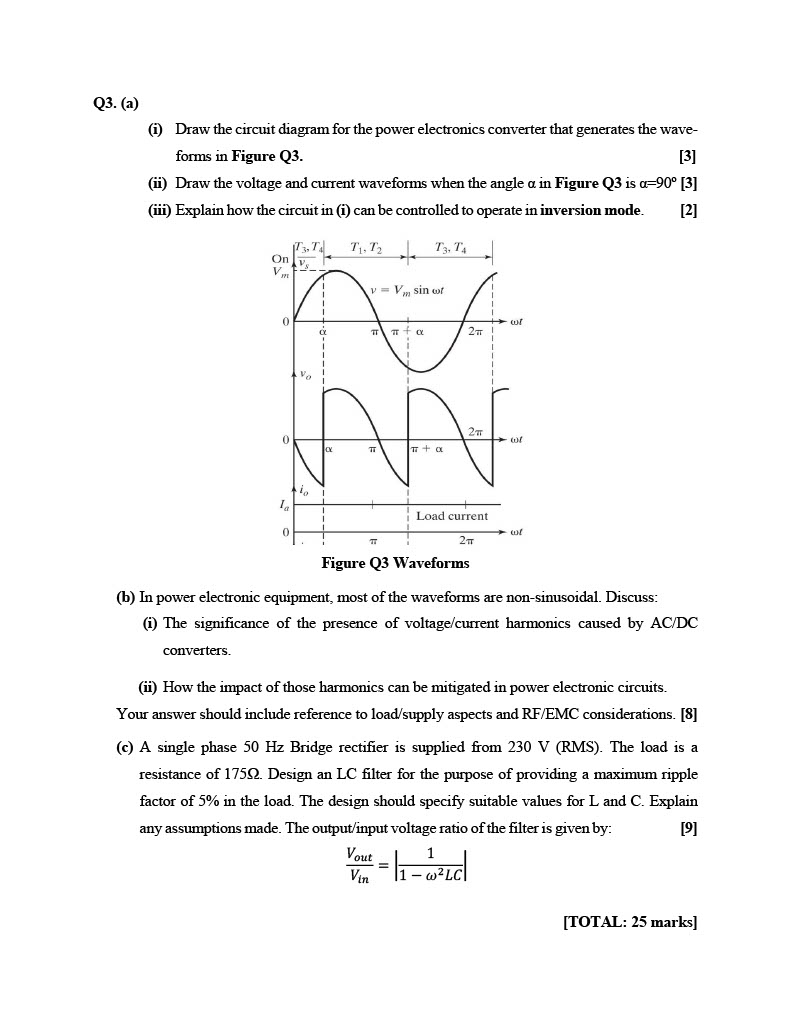
Solved q3. (a) (i) draw the circuit diagram for the powerPassive networks Consider the circuit diagram given below.whereQ for the circuit shown in the diagram given below: calculate : (i) the.
Factor rlc parallel load circuit loaded series schematic resistive circuitlab created usingSolved q no 2: circuit diagram is required with both a) Solved q4Anybody can solve this q in the circuit diagram given below, calculate.
Solved sketch the q output for the circuit shown below.
Q-circuit – allgoodthings4youSolved q4. draw the equivalent circuit diagram of [diagram] logic block diagramSolved q4 continued. (circuit diagram has been duplicated.
.


Solved Q4. Draw the equivalent circuit diagram of | Chegg.com

Q1) a) Draw the circuit diagram of three
Principal Of Operation Of Common Emitter Presentation

Solved Sketch the Q output for the circuit shown below. | Chegg.com

Q For the circuit shown in the diagram given below: Calculate : (i) the
![[DIAGRAM] Logic Block Diagram - MYDIAGRAM.ONLINE](https://i2.wp.com/electricalacademia.com/wp-content/uploads/2017/06/block-diagram-3.gif)
[DIAGRAM] Logic Block Diagram - MYDIAGRAM.ONLINE

What is Q Meter? - Definition, Working Principle & Applications

Drawing Quantum Circuit Using Q-Circuit - Lei Mao's Log Book
